-
$1,448.32
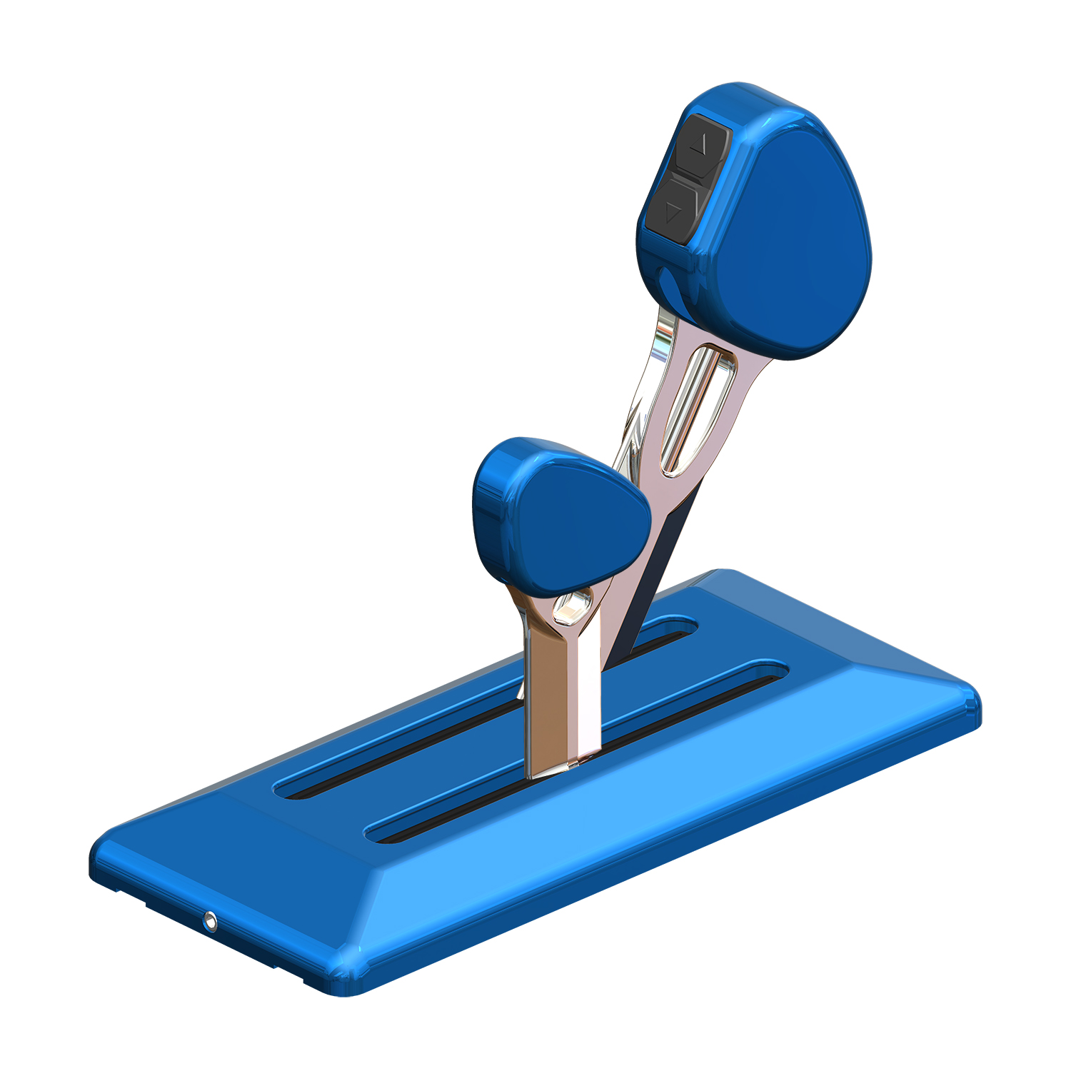
Two lever, billet short handles, one throttle, one shift for Mercury DTS engines – DTSXBS11
Select optionsIntroducing Livorsi Marine’s New QR Series™ Throttles (Quick Response) designed specifically for Mercury Marine’s DTS compatible engines. The shorter levers make this control great for tight dash spaces and allow for quicker response time. These ergonomically designed knobs are very …
-
$27.84
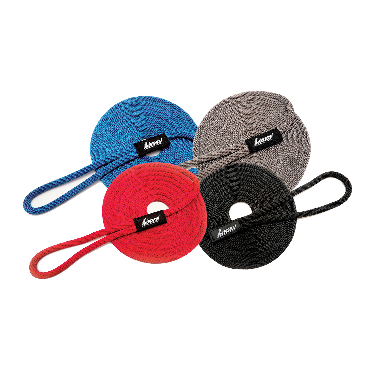
1/2″ diameter 15 foot long Livorsi dock line – DL1215
Select options This product has multiple variants. The options may be chosen on the product pageThe Livorsi Marine super soft 1/2″ diameter 15-foot long dock line is 100% manufactured in the USA. Sewn at Livorsi Marine with a Livorsi logo badge, this line has an 11″ loop for easy docking. Our dock line is waterproof and resistant to …
-
$4,500.00
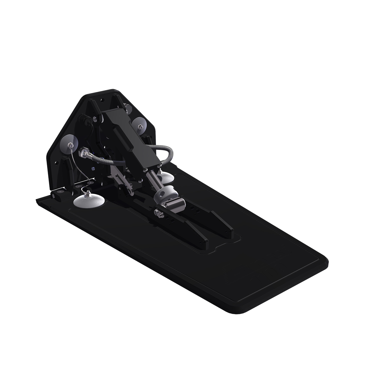
Livorsi 1100 tab with electric indication – TTK1100EL
Select options This product has multiple variants. The options may be chosen on the product pageUpgrade your boat’s performance with the Livorsi Marine 1100EL Hydraulic Trim Tab, designed for larger boats that need serious attitude adjustment.
The 1100EL features a 24″ long, 15″ wide tab, providing 360 square inches of surface area for enhanced stability and control. …
-
$4,500.00
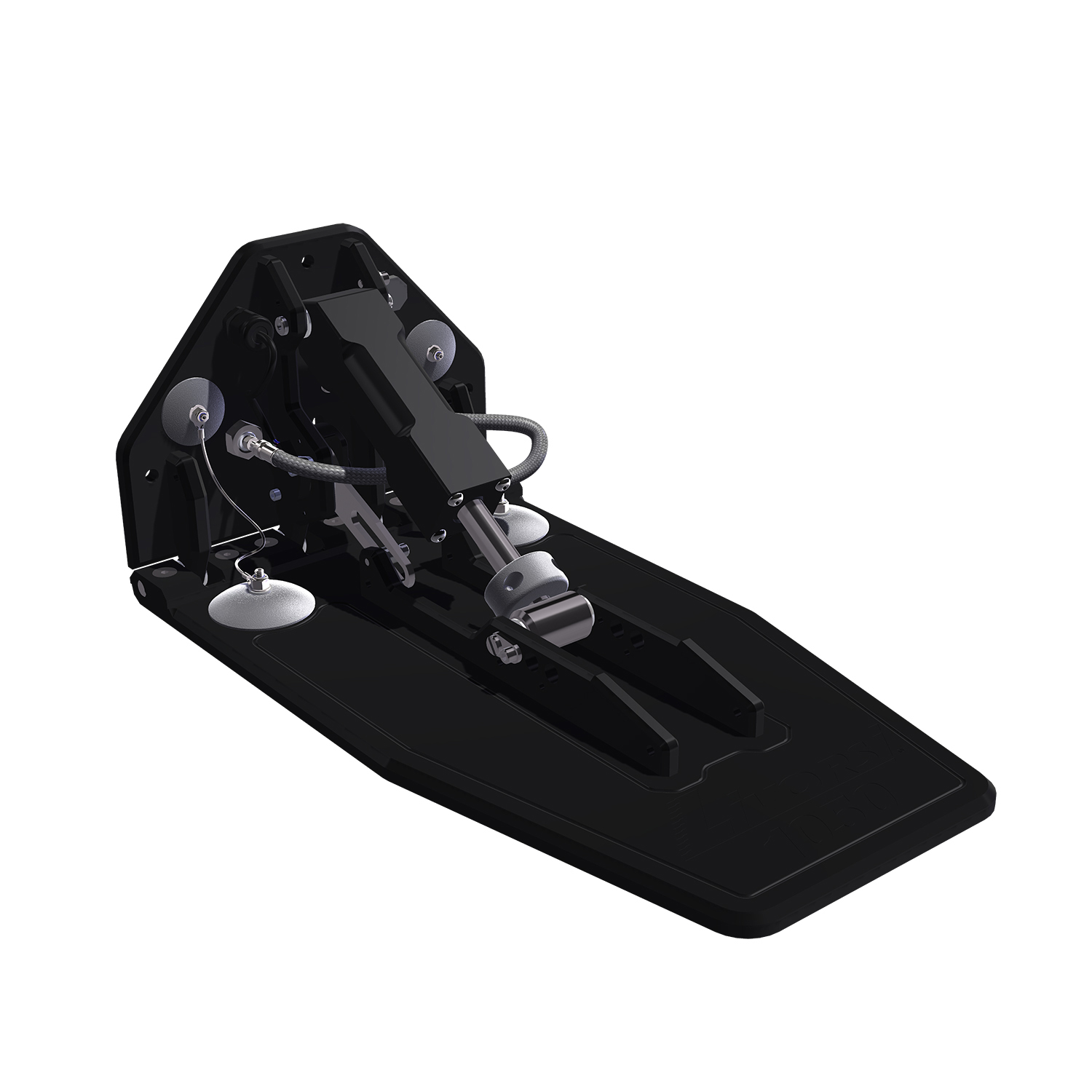
Livorsi 1050 trim tab kit with 12″ transom plate and electric indication – TTK1050EL
Select options This product has multiple variants. The options may be chosen on the product pageMaximize your boat’s performance with the Livorsi Marine 1050EL Hydraulic Trim Tab, engineered for serious attitude adjustment in compact transom spaces.
The 1050EL features a compact transom plate measuring 12″ wide and 8 ¼” tall, paired with a 22″ long running plate, providing 235 …
-
$77.50
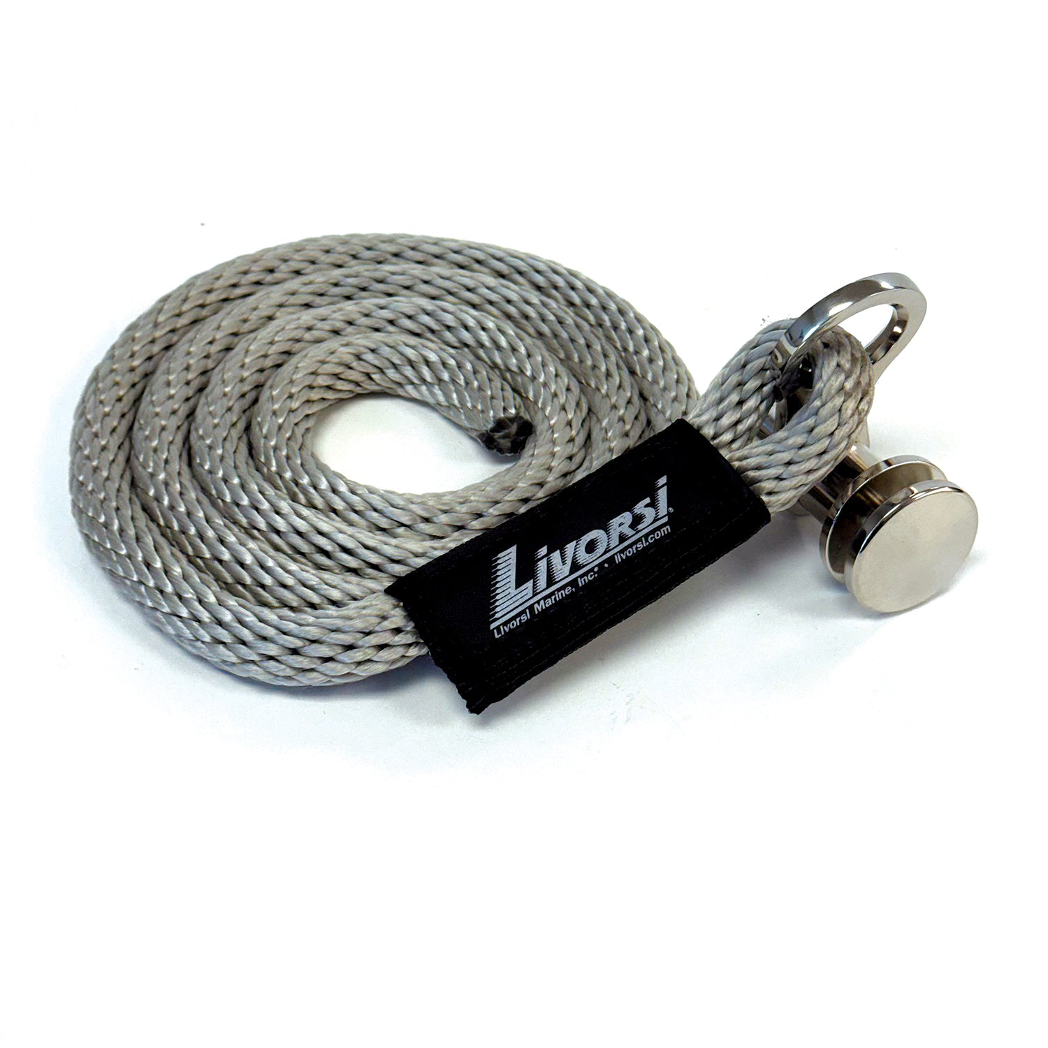
Sewn QR cleat with platinum line – QRSLFBR000048PL
Add to CartThis easy-to-use QR fender cleat has a fender line permanently sewn to our QRTFB-NL quick-release fender cleat. It also has 4 feet of American-made, platinum solid braid polypropylene rope so you can easily adjust the height of your fender. Not included …
-
$77.50
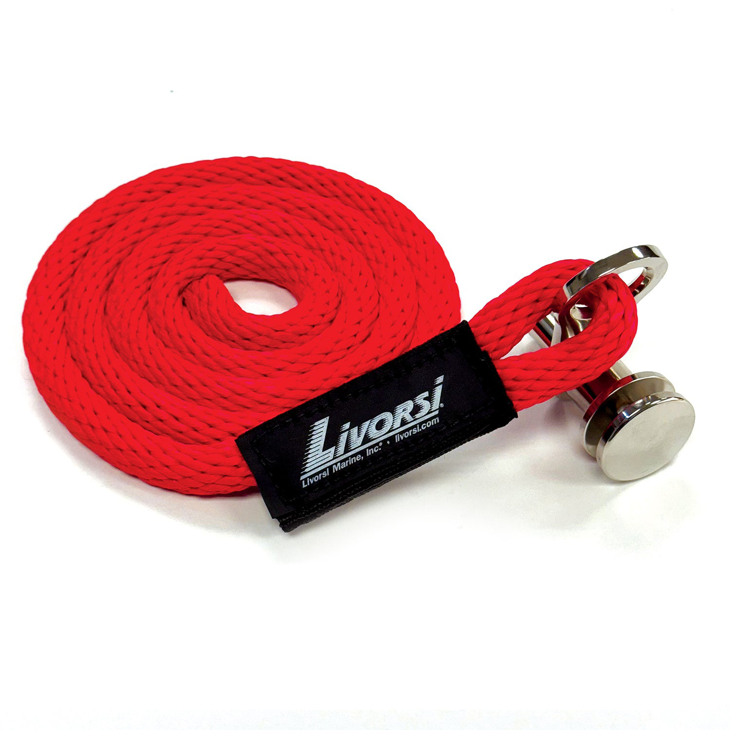
Sewn QR cleat with red line – QRSLFBR000048RD
Add to CartThis easy-to-use QR fender cleat has a fender line permanently sewn to our QRTFB-NL quick-release fender cleat. It also has 4 feet of American-made, red solid braid polypropylene rope so you can easily adjust the height of your fender. Not included …
-
$77.50
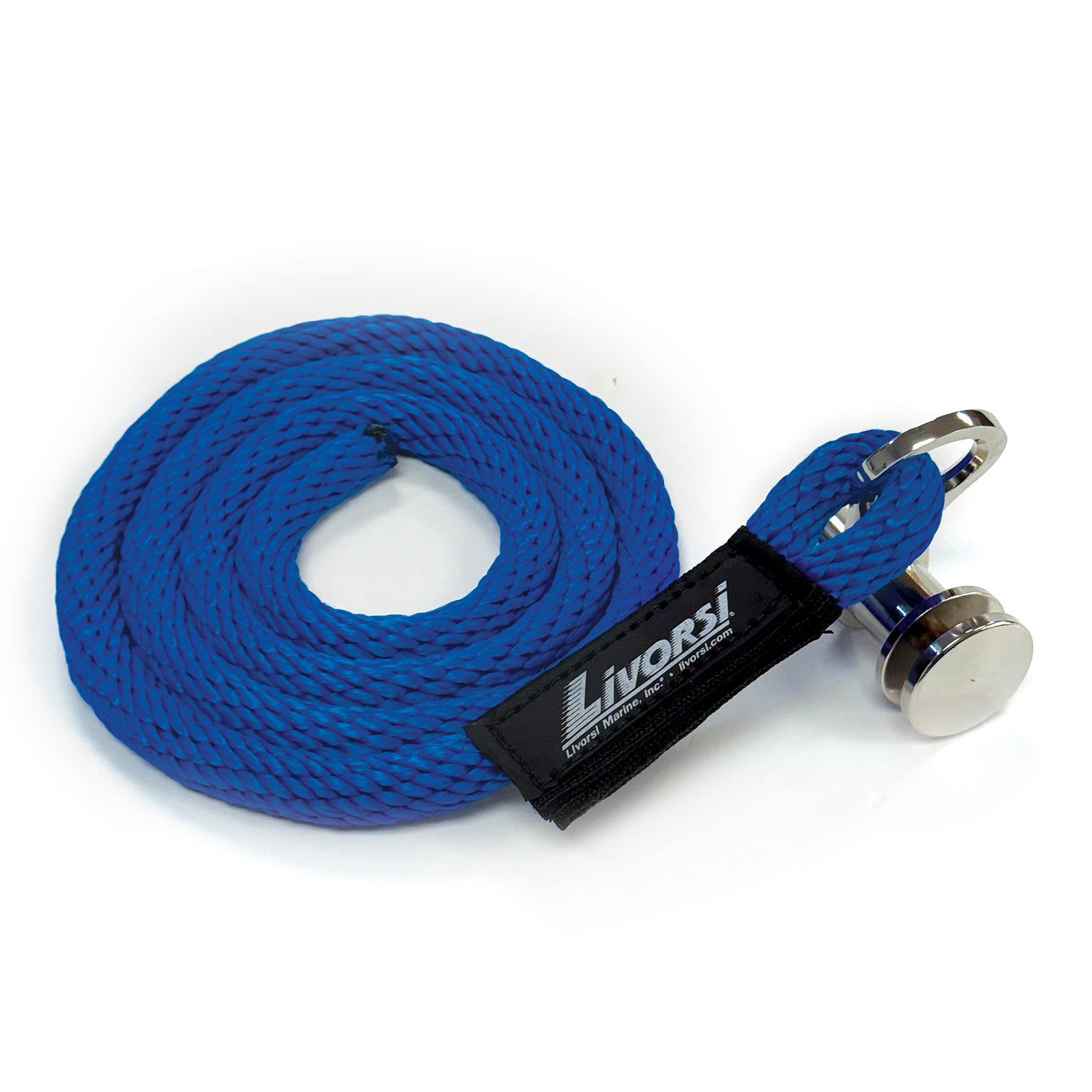
Sewn QR cleat with blue line – QRSLFBR000048BL
Add to CartThis easy-to-use QR fender cleat has a fender line permanently sewn to our QRTFB-NL quick-release fender cleat. It also has 4 feet of American-made, blue solid braid polypropylene rope so you can easily adjust the height of your fender. Not included …
-
$77.50
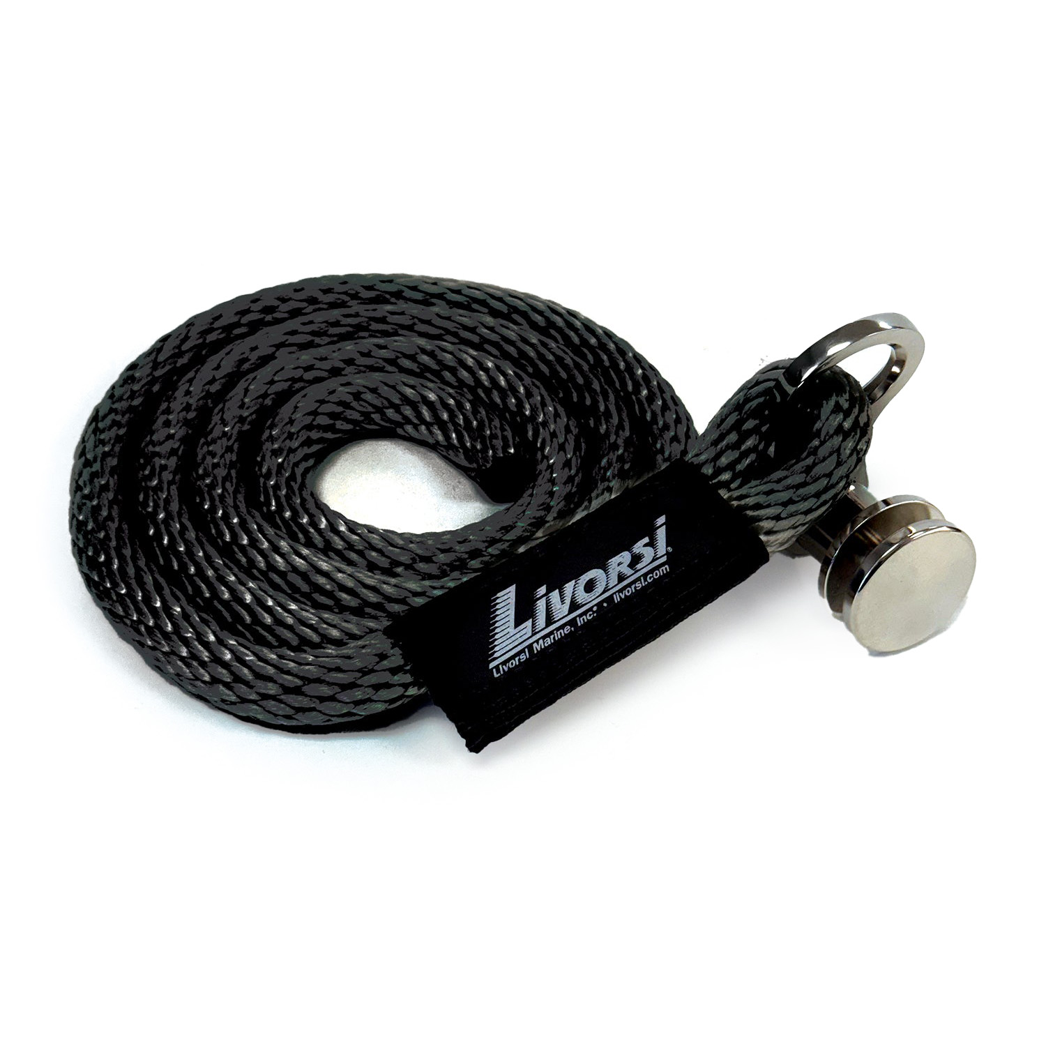
Sewn QR cleat with black line – QRSLFBR000048BK
Add to CartThis easy-to-use QR fender cleat has a fender line permanently sewn to our QRTFB-NL quick-release fender cleat. It also has 4 feet of American-made, black solid braid polypropylene rope so you can easily adjust the height of your fender. Not included …
-
$135.50
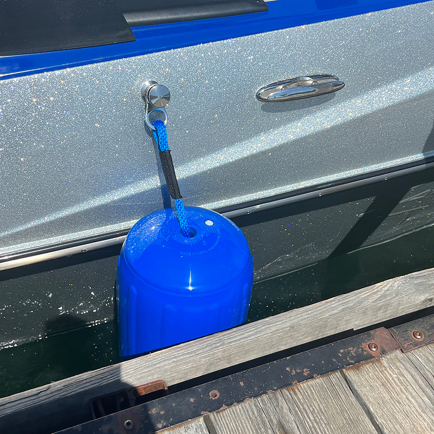
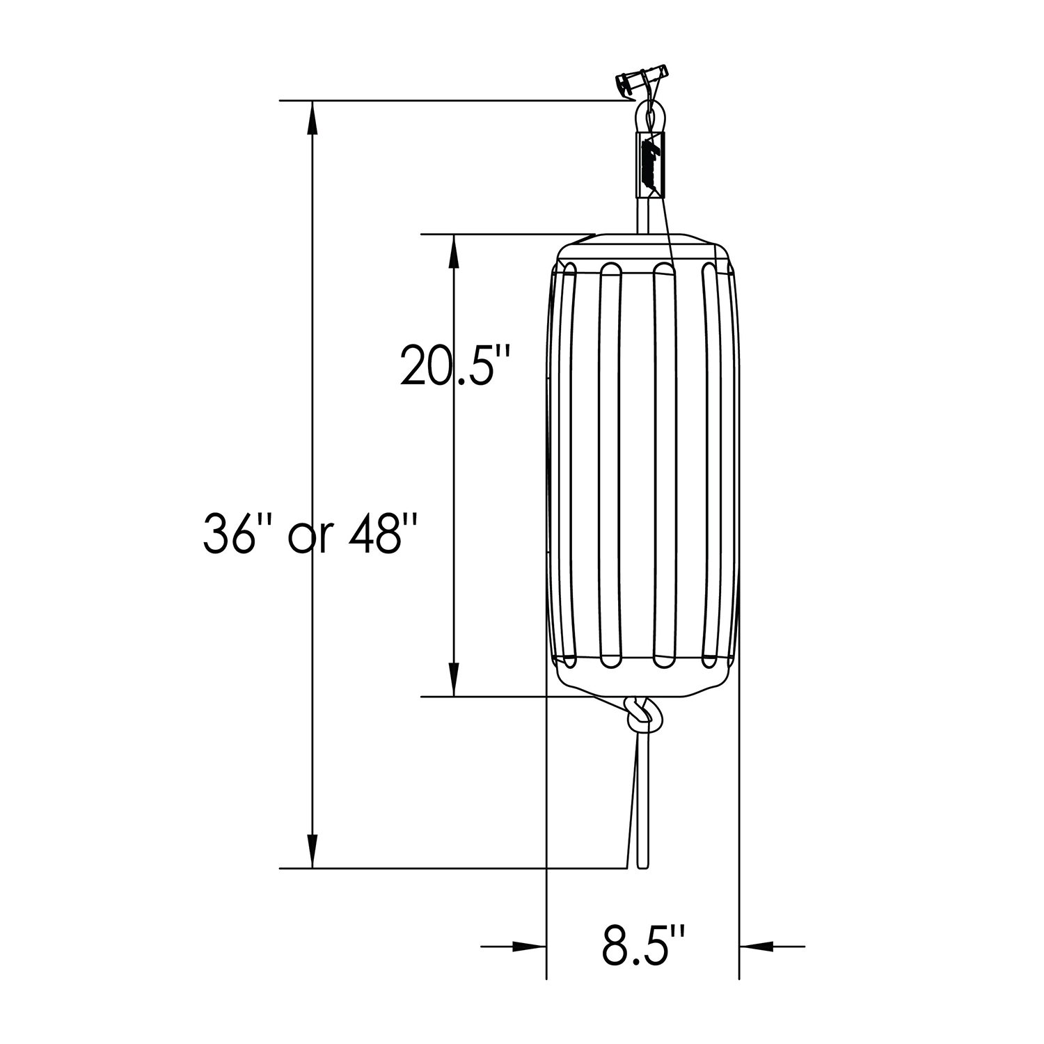
Sewn QR fender cleat with blue line and large fender – QRFB027BL215182
Add to CartNew Livorsi sewn Quick Release (QR) fender cleats make docking and tie-up effortless. Our lines are 48″ long, and when used with our hole in the middle, made in the USA fenders, they can be adjusted 20 inches up or down. Simply …
-
$449.00
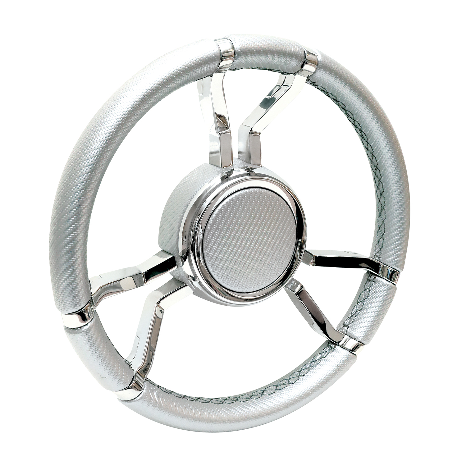
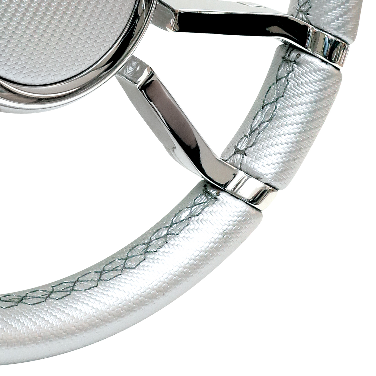
Silver carbon fiber covered Livorsi Apex wheel with polished stainless spokes – LSWL090500SXL09100
Add to CartThe Livorsi Apex Steering Wheel delivers premium style and performance for serious boaters. Wrapped in silver carbon fiber material for a comfortable, non-slip grip, the Apex is built to perform in all conditions and features platinum colored stitching. It features …
-
$38.00

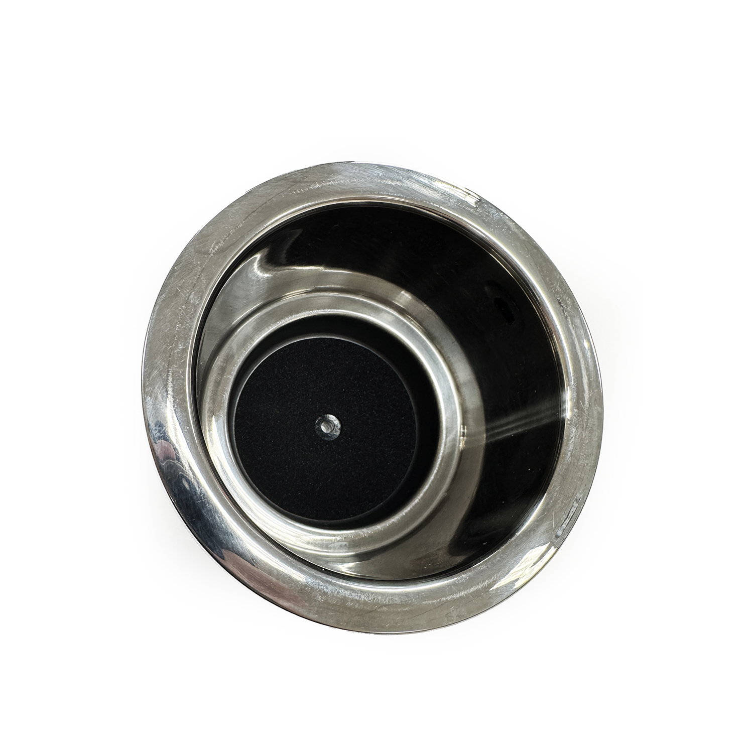
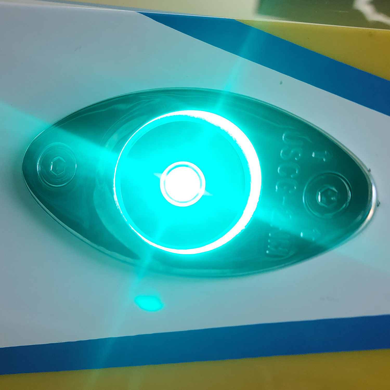
Polished stainless steel RGB, LED lit beverage holder – LBHINTRGB
Add to CartLivorsi Marine LED lit cup holders fit into a 3.5″ cutout and are 4 ¾” overall. They will fit cans, bottles, and koozies. Each cup holder has a removable rubber insert, a 3/8″ drain, and a 12″ harness to connect to your boat’s electrical system. …
-
$75.00
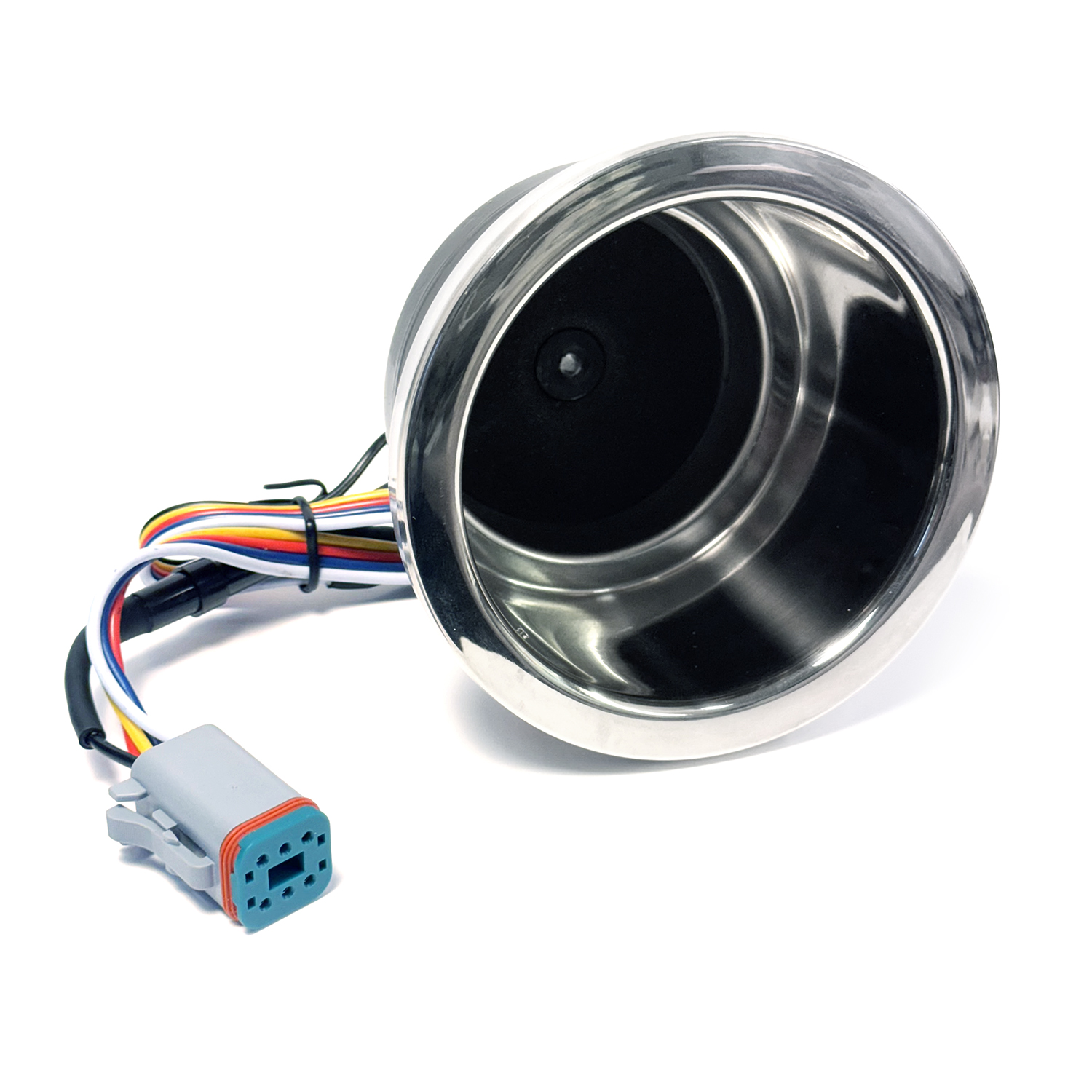
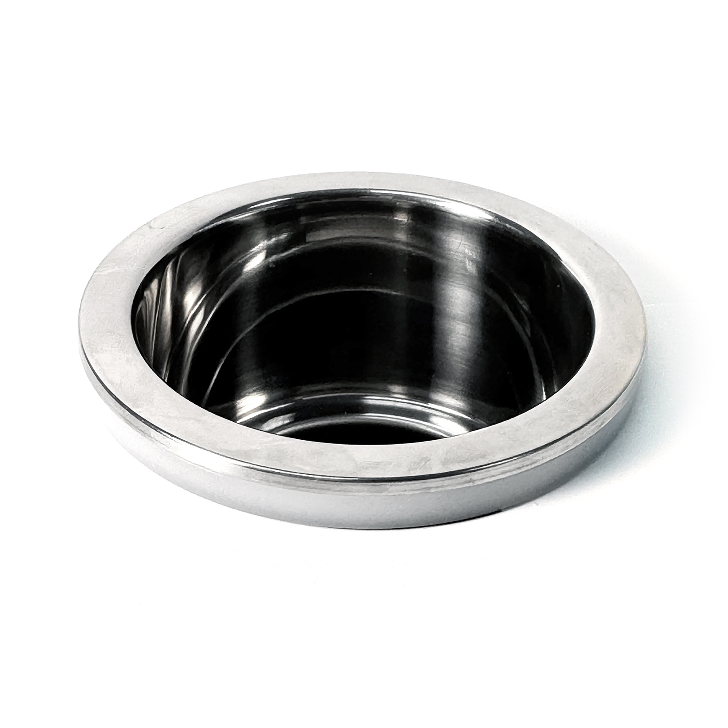
Polished stainless steel RGBW, LED lit beverage holder – LBHEXTRGBW
Add to CartLivorsi Marine LED lit cup holders fit into a 3.5″ cutout and are 4 ¾” overall. They will fit cans, bottles, and koozies. Each cup holder has a removable rubber insert, a 3/8″ drain, and a 12″ harness to connect to your boat’s electrical system. …
-
$550.00
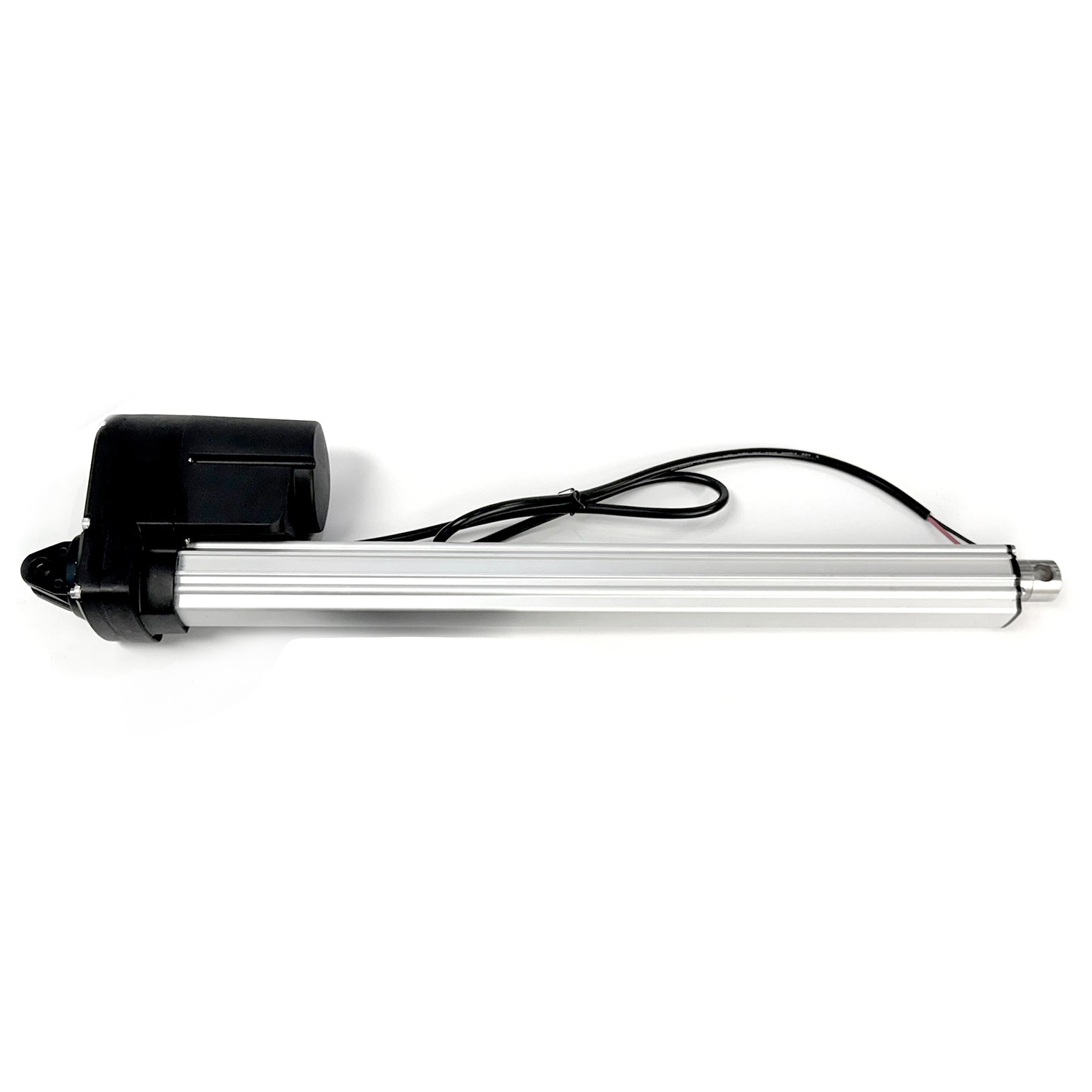
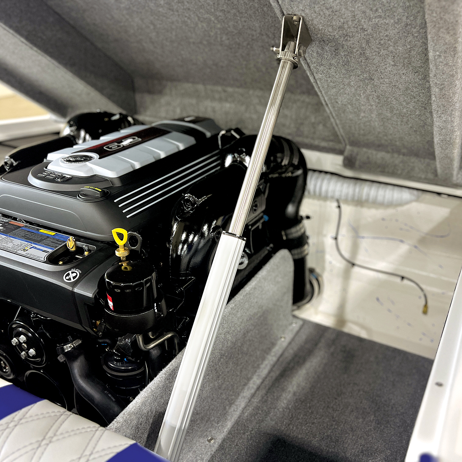
24″ stroke actuator – ACB-24
Add to Cart32.8″ in the closed position, center to center, and 56.85″ in the open position, center to center. When running at 12 volts DC, these actuators have a push and pull force of 450 lbs.
-
$518.00
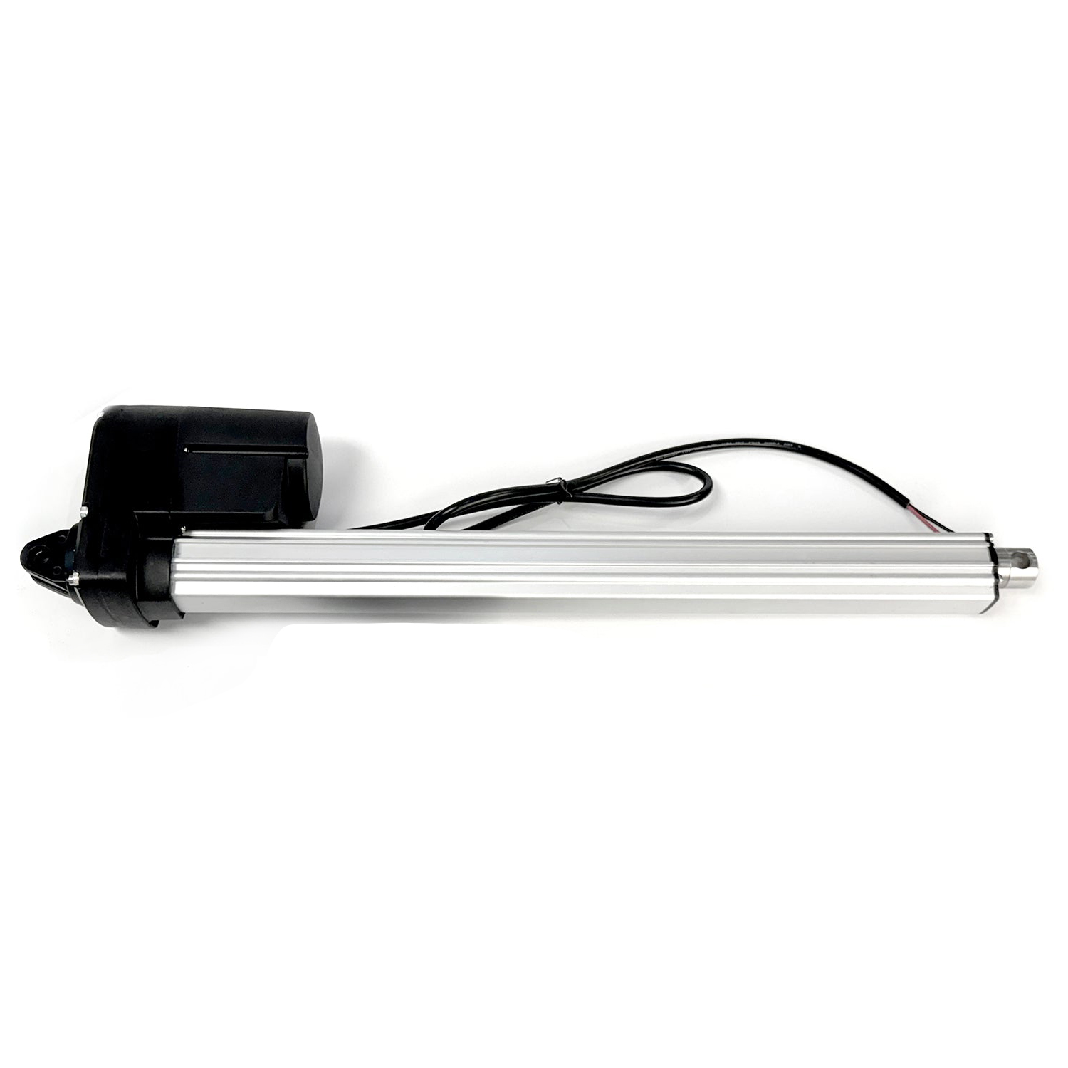
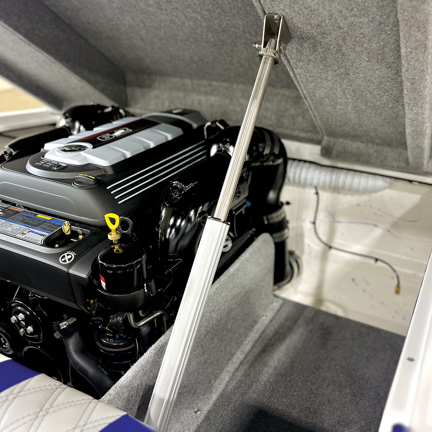
18″ stroke actuator – ACB-18
Add to Cart25.75″ in the closed position, center to center, and 43.75″ in the open position, center to center. When running at 12 volts DC, these actuators have a push and pull force of 450 lbs.
-
$499.00
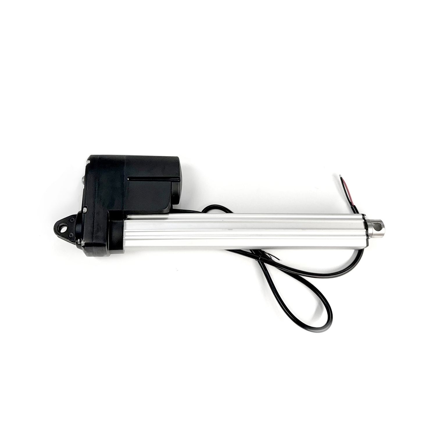
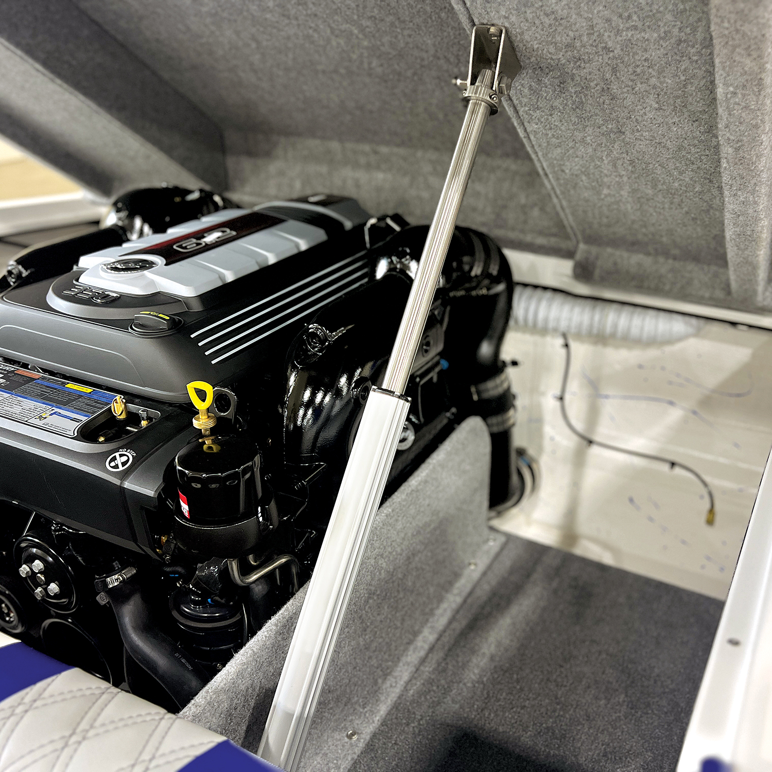
12″ stroke actuator – ACB-12
Add to Cart19.6″ in the closed position, center to center, and 31.56″ in the open position, center to center. When running at 12 volts DC, these actuators have a push and pull force of 450 lbs.
-
$2,349.58
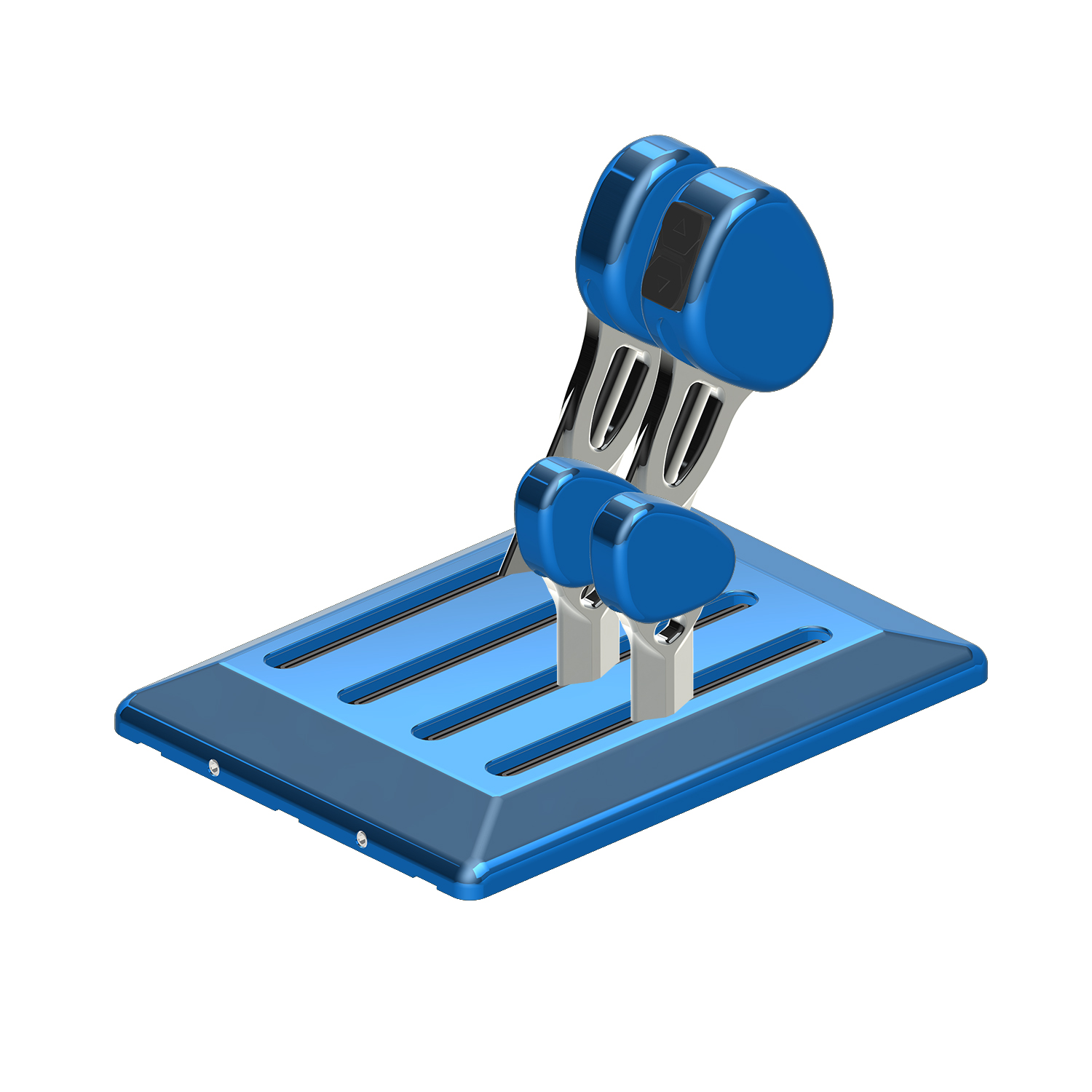
Four lever, billet short handles, two throttle, two shift, for Mercury DTS engines – DTSXBS22
Select optionsIntroducing Livorsi Marine’s New QR Series™ Throttles (Quick Response), designed specifically for Mercury Marine’s DTS compatible engines. The shorter levers make this control great for tight dash spaces and allow for quicker response time. These ergonomically designed knobs are very …
-
$50.00
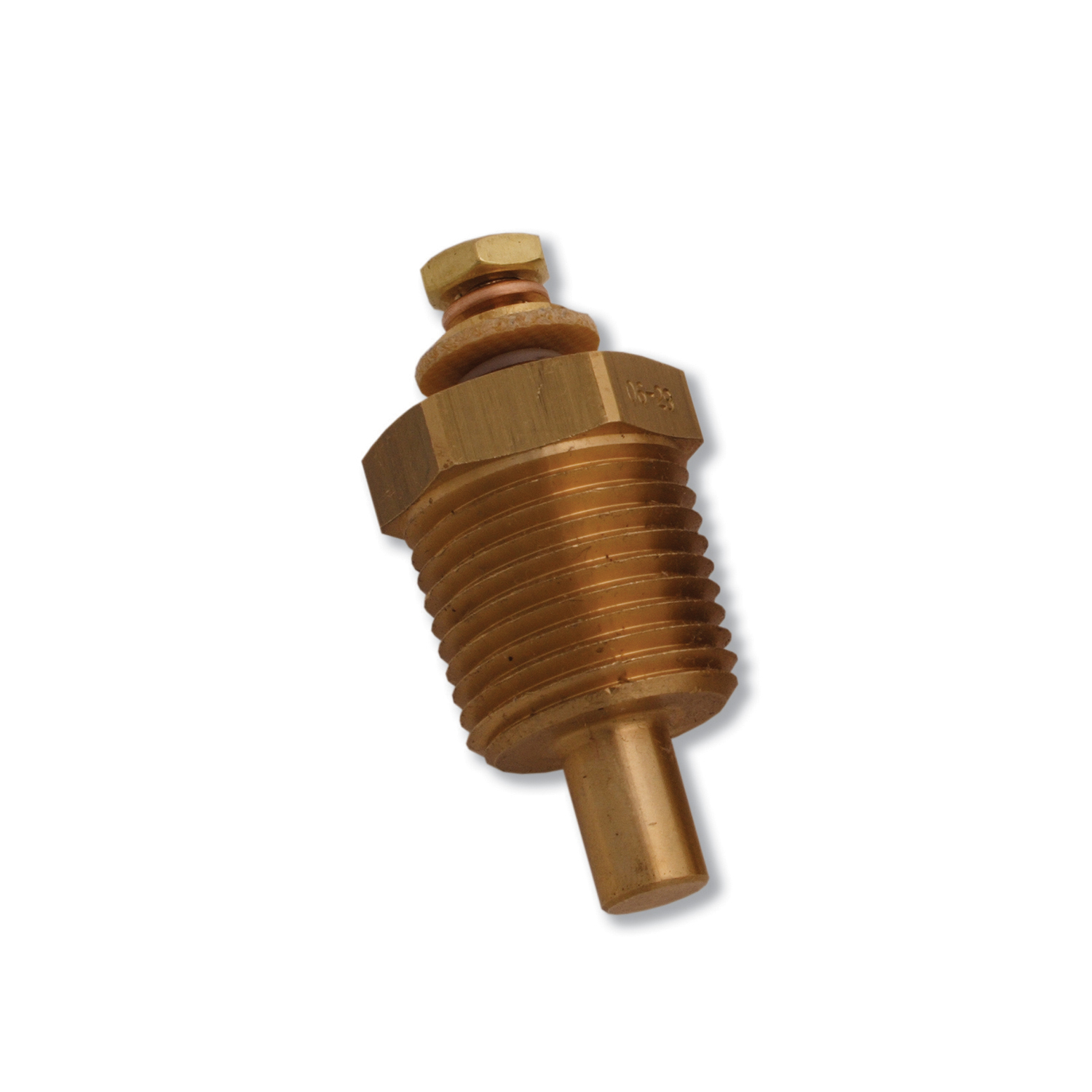
Water temperature sender 3/8″ NPT – GSWT3/8
Add to CartThis analog temperature sender works specifically with Livorsi analog 100-280° F Water Temperature gauges. This sender connects to the engine block with a 3/8″ NPT thread. When installing the sender for your gauge onto the engine, do NOT use any sealant …
-
$40.00
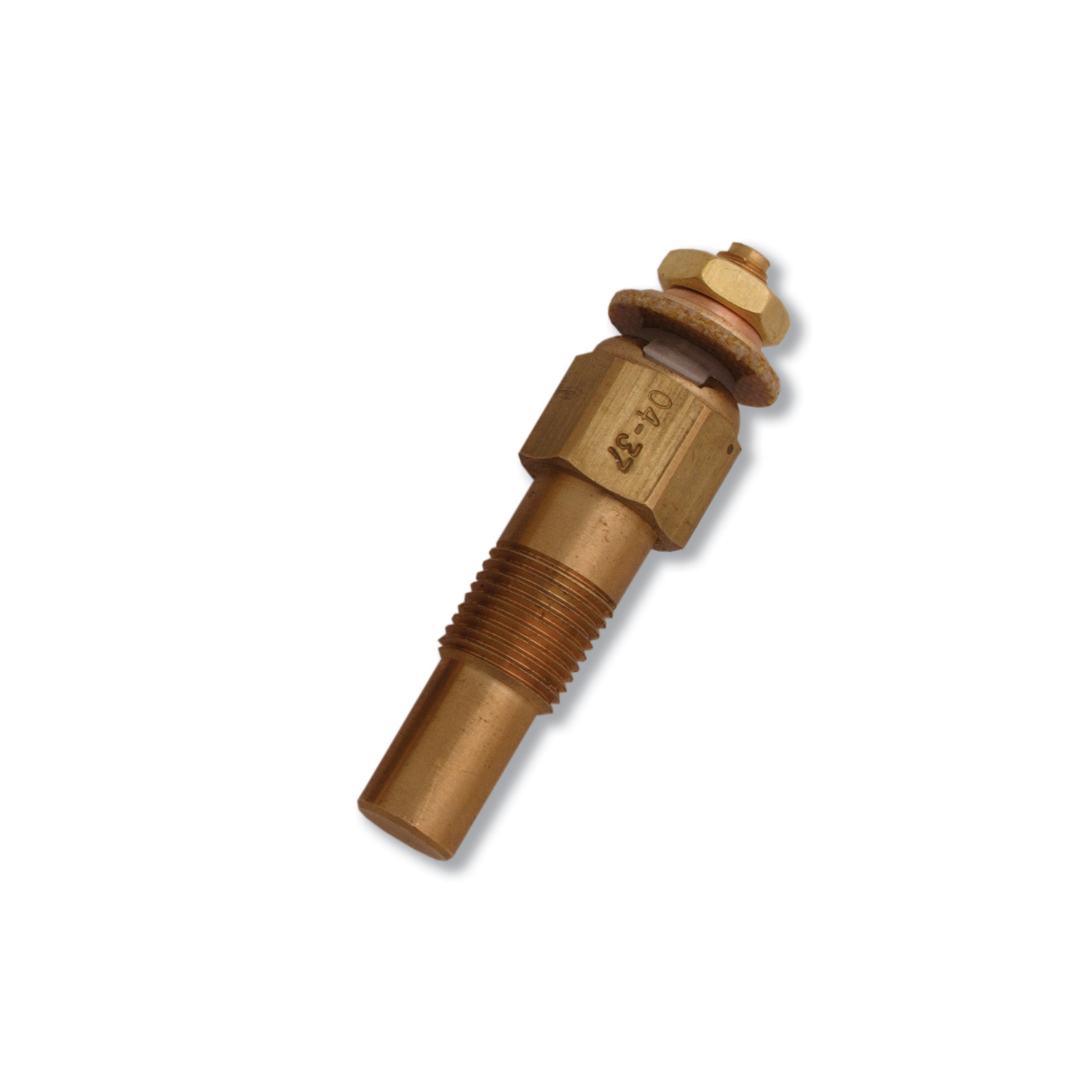
Water temperature sender 1/8″ NPT – GSWT1/8
Add to CartThis analog temperature sender works specifically with Livorsi analog 100-280° F Water Temperature gauges. This sender connects to the engine block with a 1/8″ NPT thread. When installing the sender for your gauge onto the engine, do NOT use any sealant …
-
$50.00
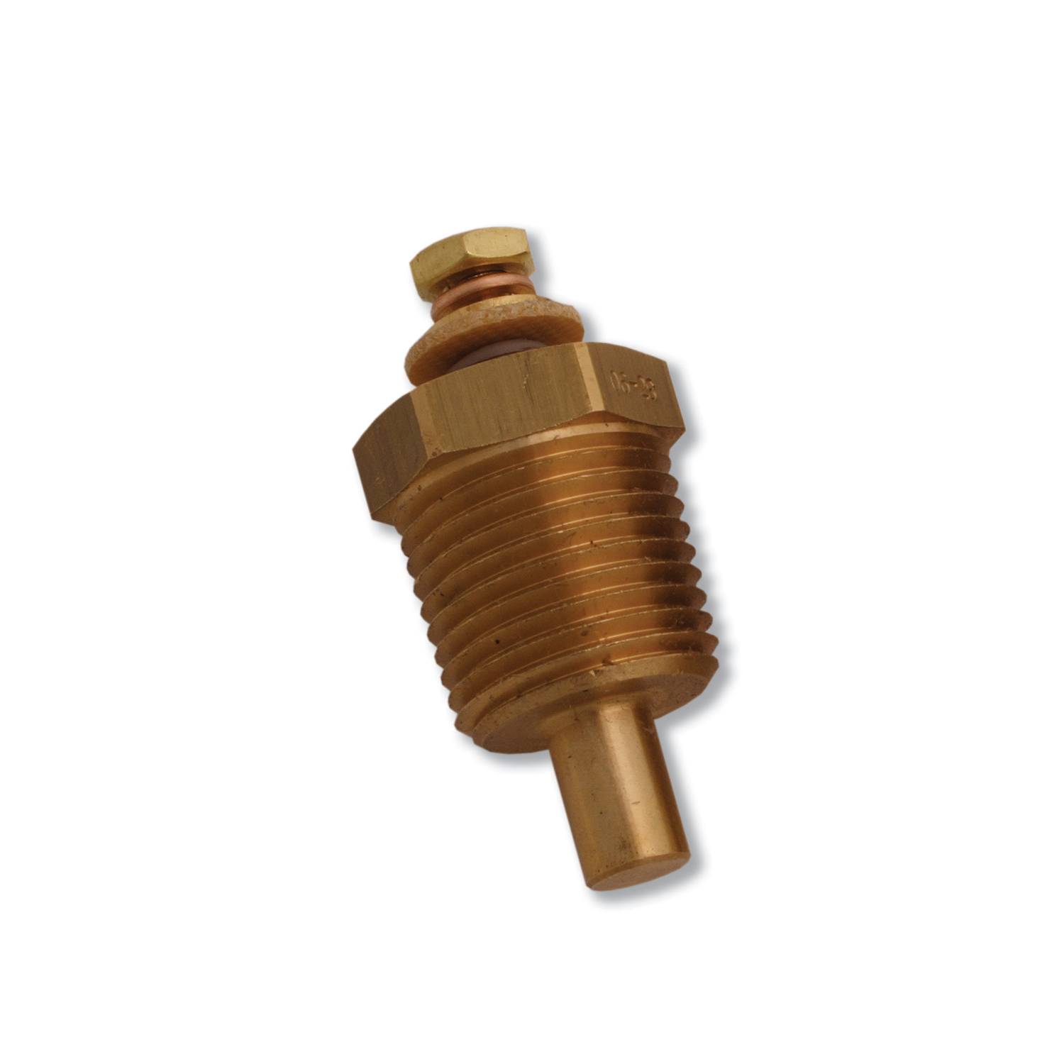
Water temperature sender 1/2″ NPT – GSWT1/2
Add to CartThis analog temperature sender works specifically with Livorsi analog 100-280° F Water Temperature gauges. This sender connects to the engine block with a 1/2″ NPT thread. When installing the sender for your gauge onto the engine, do NOT use any sealant …
-
$699.51
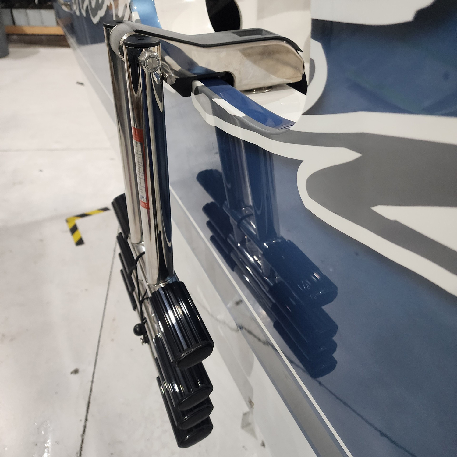
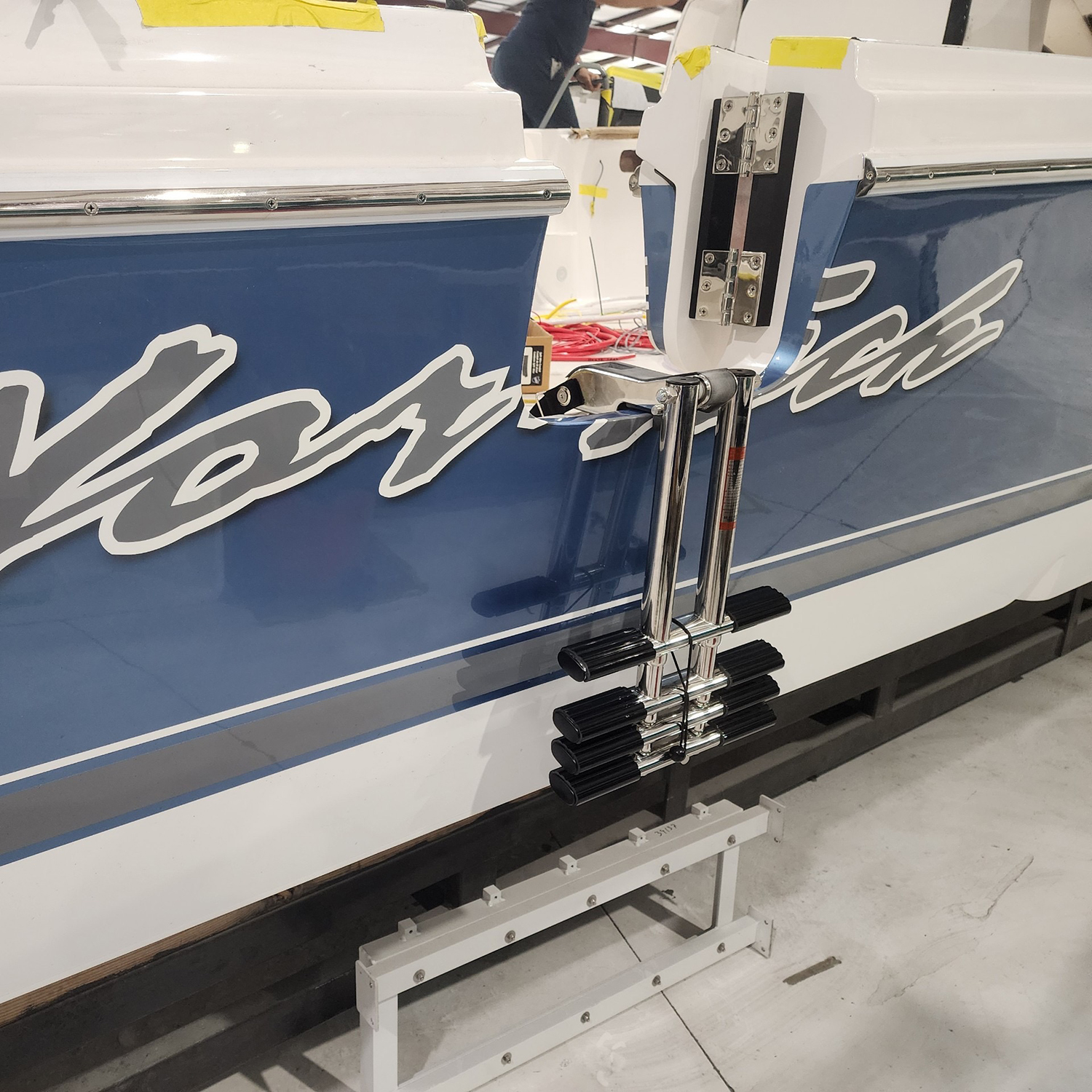
Single pin quick release short base retractable ladder – QRL4SCLA-N
Add to CartOur versatile ladder is designed for convenience. It easily engages and disengages with Double Action QR Pins, allowing placement anywhere on your boat in multiple locations. It features a four-step extension reaching up to 46 inches for effortless boarding. Crafted from …
-
$578.75
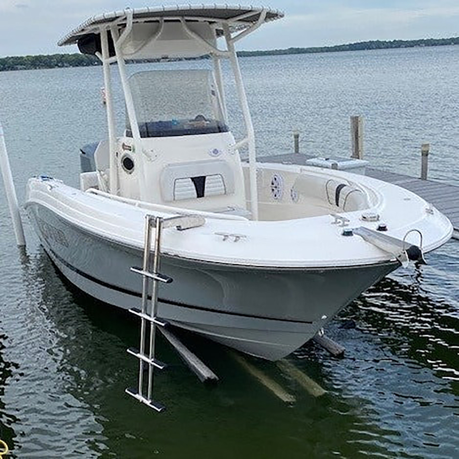
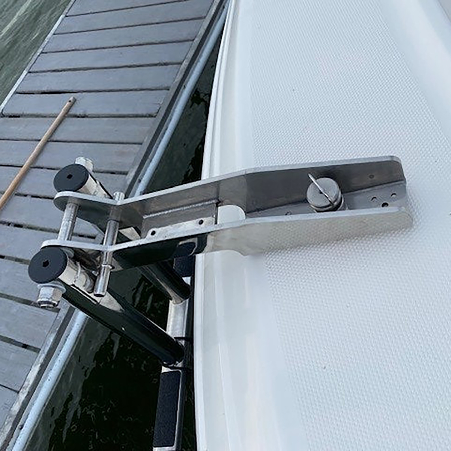
Single pin quick release retractable ladder – QRL4SCLA
Add to CartOur versatile ladder is designed for convenience. It easily engages and disengages with Double Action QR Pins, allowing placement anywhere on your boat in multiple locations. It features a four-step extension reaching up to 46 inches for effortless boarding. Crafted from …
-
$164.95
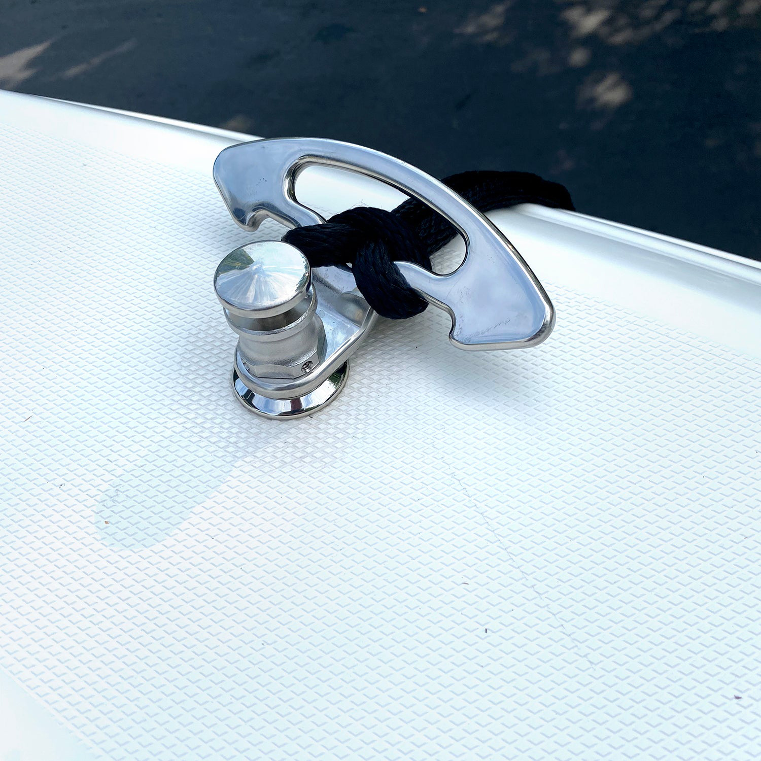
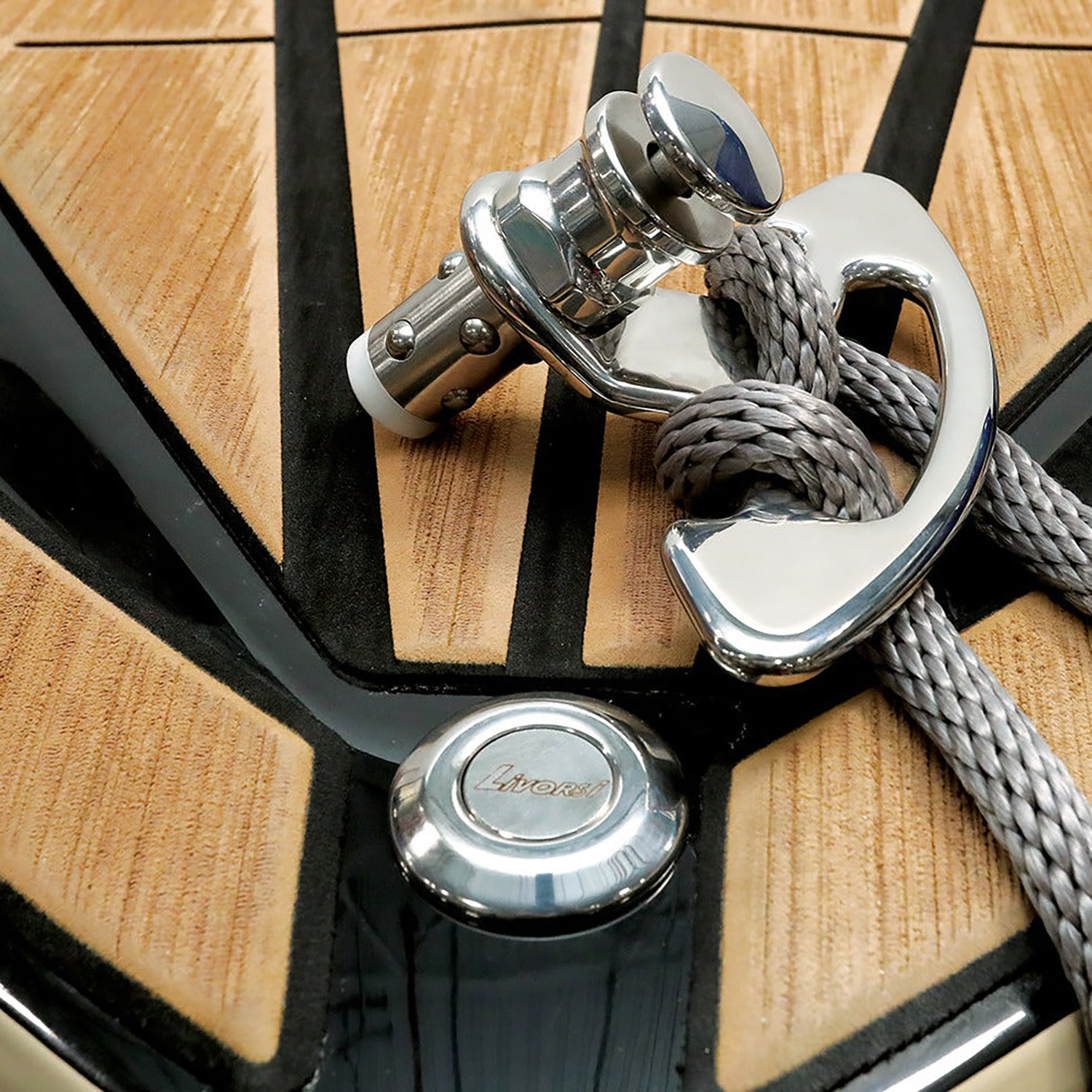
Quick Release Boat and Dock Cleat Kit – QRKLC2RLBWD4-375-L01
Add to CartThis polished 316 stainless steel quick release boat and dock cleat kit requires a 1.25″ hole in the boat or dock, as well as access to tighten the bolt to hold it in place. These cleats are easy to install and use, …
About
At Livorsi Marine, we design and manufacture high-performance parts and accessories for all kinds of boats. From weekend cruisers and towboats to military and commercial vessels, our products are built to perform, look sharp, and last in tough marine environments.
Capabilities
Simple things like adding a logo, applying a custom color to design from scratch new products can all be done with the vast resources found at Livorsi Marine.
